ATS Advanced Turn Signal Systems
1996-2004 Mustang
(c) 1997 Marvin Davis
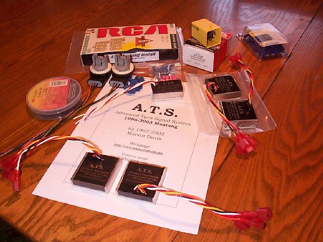
Parts kit inventory list for 1996-2004 Mustang
2 ea. ATS-III sequential hi-power lamp controller.
2 ea. Ford F50B13411CA brake/turn signal lamp socket.
1 ea. SF-609 (F67Z-13350-AA) Turn Signal/Hazard Flasher (modified)
1 ea. T&B Industrial fully insulated Male/Female connector set.
1 ea. roll of 3M/Scotch electrical tape (to re-wrap harness)
Recommended tools and supplies for installation
1 ea. 11-MM short open end wrench.
1 ea. wire strippers or sharp pocket knife.
1 ea. T&B "U" shaped jaw wire crimpers. (see Note:4 in Appendix)
2 ea. 3157LL brake/turn signal bulbs (if not available in
use on existing parking bulb socket to be replaced)
Krypton bulbs are now available as an order option or from G.E. Automotive lighting. Since you are going to have the light assemblies out (time consuming to a point to remove to change just one burned out light bulb), it makes good sense to go ahead and install the brighter and 2X longer life (double over stock) KPYPTON lamps.
Basic Installation on 1996-2004 Ford Mustang
[1] Open trunk and remove rear trunk liner retainers (approx. size of a quarter) from both sides.
[2] Carefully peel back trunk liner and remove 4 ea. 11 MM nuts that hold in the rear lens assembly.
[3] Lay soft towel or cloth on rear bumper and pull out lens assembly and lay face down on cloth with the rear facing up.
[4] Locate wiring harness pin anchors and pull out to free wiring. Using a knife, cut along edge of plastic anchors to remove all vinyl tape up to about 2-3 inches from rubber trunk grommet.
[5] Remove inboard (parking light) socket and place out of way and move outboard brake light socket to now inboard empty socket and install. (If unfamiliar with the terms inboard or outboard, see TERMS in appendix A)
See NOTE:1 in appendix for additional parking light position info.
[6] Cut BROWN and BLACK wires flush on old parking light socket and remove bulb (verify it is a dual filament brake/turn & parking bulb). Ford has been using the same bulb type in rear sockets. We will reuse it if its a dual filament type bulb.If not, you will need to purchase two additional #3157 brake/turnsignal light bulbs to complete installation)
[7] Place bulb in NEW dual filament socket and now install in outboard socket hole.
Note here that the wiring colors need to be uniform on the new sockets and the side you are working on.
Below is the color code(s) per rear side;
|
Driver |
Passenger |
| Green/Org stripe = Brake/Turn signals | Orange/Gray stripe = Brake/Turn signals |
| Brown = Parking lights | Brown = Parking lights |
| Black = Ground | Black = Ground |
[8] After noting wire colors for identification you take BLACK on new outboard socket plug and BLACK from the previous parking light and strip 3/8" insulation off, twist them together and crimp them in a female connector.
[9] Take BROWN from old parking light and using splice connector make up with BROWN on new outboard plug socket. This makes up the parking light circuit.
[10] Measure approx. 5 in.'s up from the middle brake socket wire (note the color code chart above for the side you're working on for brake/turn signal wire color) and cut wire and strip insulation off of both cut ends. Place female terminal connector on brake/turn signal wire going to socket.
Also, place female connector on other cut end going back up to trunk grommet. This is the brake/turn signal power feed.
[11] Check/verify wiring so far. You should have three wires with female terminal connectors on the wiring harness, and the splice connector (brown) going to parking light(s). The remaining brake/turn signal wire on new socket will be made up after mounting controller and spotting for wire length for cutting and making up this socket connection(s).
[12] Mount ATS lamp controller on inside bottom corner of lens bucket after cleaning area well with rubbing alcohol to ensure adhesive strip sticks properly. Attach lamp controller with wires sticking straight up and unit in corner "flat" next to inboard lamp.
The 3M adhesive tape will anchor the module in place and since the module is "sealed" there is no need for concern about moisture.
[13] Note the following chart for making up connections to controller:
Make up ATS controller with the following using female connectors ;
(a) BLACK on controller to BLACK on wire harness.
(b) YELLOW on controller to middle #2 brake light socket. (note wire color(s) per driver or passenger rear side)
(c) ORANGE on controller to outboard #3 brake light. Lay brake/turn signal wire along harness to spot for correct
length, cut/strip and crimp female connector and plug in.
(d) RED on controller to incoming BRAKE power feed (last wire left noting wire color(s) per driver or passenger side).
[14] To quick test the controller, have someone press and hold the brake pedal and note the three lights come on in sequence and stay on. If not, recheck all your connections and wiring terminations to ensure controller is being powered and the sockets/lights are good.
[15] Re-use plastic harness anchors and spot them on harness for position and wrap electrical tape starting in an "X" pattern around the anchor and move down the wiring, wrapping as you go. You can use the plastic tywraps included to aid you in spotting the anchors on the harness or holding the harness together while re-taping it. When completed, you should have wrapped all exposed wiring and connectors so that when looking at the harness it looks like "factory". The anchor pins serve
to secure the wire harness in place so it does not move around.
[16] When complete, place lenses back into body and snug up the four 11 MM nuts. *Do not over tighten*. Then move over to opposite rear side and remove those four bolts and lay the lens out on the bumper with a soft cloth underneath. You now start back at STEP 4 and begin the install procedure for that side. The only thing different will be the wire color for the brake/turn signal feed as noted above.
[17] When completed on rear wiring, install new flasher box under the dash. With flashlight, lay on left shoulder and shine light up under hump on drivers side and you will see the YELLOW flasher box. It's mounted on a flat tab and can be removed by pulling slowly and firmly straight down at the same angle it is mounted in.
Once it is off the tab, you can place a small flat tip screwdriver into the retainer clamp and pull the plug off of the bottom to detach it from the wiring. Now snap the plug on the new one and slide it back up onto the metal tab and you are done with the flasher installation.
Note: On the 1998 model the flasher is located just above the "foot rest" to the left (right next to the fuse box). It mounts
sideways (rather than up & down) on the metal support tab.
[18] Start the car engine and place the emergency flashers on and note all brake/turn signal filaments should be on in a inboard going outboard sequence. This tests all rear the functions of the ATS controllers. See NOTE:2 in appendix for info.
Test rear parking lights and backup lights to ensure other rear lighting are functioning normally.
This concludes the basic ATS sequential lighting system installation for late model Ford Mustang.
Disable feature/option
NOTE: For those who purchased the ATS controllers with the active 'disable' feature, the fifth or white wire is for forcing the controller into a 'stock' operation. This is normally tied to the other modules white wire and is fed via a toggle/rocker switch that is powered off of the Ignition or Accessory circuit. If you have "traffic backers" or other 3rd. party rear lamp controls you want the disable feature to be powered when these devices are in operation. In this way, the ATS system will not interfere with its operation, as the controllers will work the lights in a stock fashion.
Theory of Operation
The ATS sequential turn signal system operates in a simple way. The inboard brake/turn signal bulbs are kept in stock operation and are not controlled in any way. The ATS lamp controller is powered when wired in parallel with the
inboard bulb(s). When Brake, turn signal, or hazard flasher power comes back to turn on the inboard bulb(s), the controller is powered and then does a precision delay on the two outputs (#2 and #3) to fire these at approximately 200 ms delays. Once the lamps are turned on they will stay on as long as power is applied to rear lights. The delay or control is only on energizing the bulbs, once on they are left on.
The other "timing" control in the system is the turn signal control flasher. The one supplied in the kit has been modified to change its delay from 80-90 FPM (flashes per min.) to a slower 40-50 FPM. This is to have a longer Flasher time delay to have the last controlled bulb time to stay on to full illumination before cycling off to start the next turn signal flash sequence.
ATS controller modules have built in safety shutdown in case of low supply voltage. This is to conserve/save battery power if the car is left on hazard flashers for an extended period of time. When using up to 10 ea. #3157 bulbs, you will be pulling up to 23-25A off of your battery and this is as much demand as leaving your headlights on with the engine off. If such conditions occurs, the controller will start to shut off the controlled lights and as soon as normal supply voltage is restored they will work normally again.
Periodic Testing :To test all rear brake and turn signal bulbs, simply engage the emergency hazard flasher and walk around the car to check all turn signals and brake lights at one time.
Appendix A
TERMS!
The term "inboard" is in reference to the vehicle center line.
or taillamp closest to the license plate. The term "outboard" is in
reference to the lamp farthest to the outside or away from center line
or vehicle license plate.
NOTE:1
Note the location of the parking light socket to be changed on your particular model Mustang. Late models use the inboard sockets to house the parking light socket(s), earlier models use the outboard sockets to mount the parking lights. If parking lights are outboard, mount the NEW brake/turn signal socket in this location to populate the required three brake/turn signal lights per rear side.
NOTE:2
Final checkout should be done with the engine running to ensure full
power supply voltage to the rear harness. If operating on battery
power alone, voltage may be low enough to prevent the controller(s)
from firing all lights due to designed low-voltage shutdown feature.
NOTE:3
Tywaps are included to aid in spotting the spearhead anchors and to
hold the harness neatly together while re-wrapping with electrical tape.
You want the installation to look factory like and professional.
NOTE:4
The crimping tool recommended is one used by industrial electricals and
technicians. You can use generic crescent shaped jaw crimpers but care
should be taken when making connections as you may have to use much more
force in squeezing the connector on the wire to get a good solid connection.
Since one size terminal is used in the kit (large enough to place two wires for connections) you can strip back 1/2" of smaller gauge wires and fold the end over double (to 1/4") and place this end into the terminals to crimp. This does provide more copper to crimp down on and make for a better mechanical connection as well.