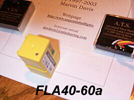
FLA40-60_A
Adjustable Speed Turn Signal Flasher Module
ATS Lighting Systems © 2003 Marvin Davis
Due to increasing demand for end user flexibility in adjusting the ATS Lighting System’s look to suit individual taste, you can now purchase a sequential lighting kit system with a standard OEM replacement turn signal flasher module with a calibrated precision adjustment feature.
Please read all the following text and guidelines to ensure you understand the units operation and how to adjust for personal tastes within its designed range.
Any speed adjustments should be done with the engine running to ensure full power level to the rear harness and flasher module. When replacing the stock factory unit, leave the new unit loose or unmounted and its connector plugged in so you can easily access the speed adjustment.
When completed, you then slide and lock the flasher module on its factory mounting tab under the dash and you are done.
The Advanced Turn Signal (ATS) lighting system has been designed to work its own electronic design modules and new adjustable flasher in concert to allow a setup range from 40 to 60 FPM (+/- 2 flashes per min) whereby the optimum for equal or symmetrical look is 50 FPM. This would relate to "medium" or midrange speed setting. These adjustable units are shipped and setup for midrange or "medium" speed. Below are examples of range or speed settings in FPM (flashes per minute);
40 FPM ( slow, last or outside lamp stays on an additional 200ms)
50 FPM ( medium speed, lamp staging and flasher ON/OFF times equal )
60 FPM ( Fast speed, outboard lamps come on to full brightness and recycle )
The small adjustment trim (potentiometer) is setup for 10 turns giving exactly 20 FPM range adjustment to the system. It is shipped setup for medium speed (50 FPM) and allows the installer to increase or decrease the turn signal cycle speed for desired look. Each 360 deg. turn of the trim adjustment screw is equal to 2 FPM.
If you are going to make speed adjustments, knowing that you are in the exact center (middle) of the trim screw range, you can then do the following;
CW (clockwise to increase speed, 1/2 screw turn equals 1 FPM )
CCW ( decrease speed, 1/2 screw turn equals 1 FPM )
So for example, if the initial look is a little fast for your taste, and you wish to make a change to slow the turn signal action down, you wish to decrease the speed by say 5 FPM. You would turn the trim screw exactly 2 ½ turns CCW and then check the speed or look (time/count flashes for 30 sec’s and multiply by two to get the FPM rate). This would result in a system speed of approximately 45 FPM.
If you reach either end of the speed adjustment range, the trim screw will continue to be turned but no speed change will take place. This is why you want to observe and pay attention to where you start and note the direction and number of turns you have adjusted. If you loose track of what you are doing and wish to know what setting you currently have, you can time the number of times the turn signal flashes for a 30 sec. time period and multiply by two to obtain the current FPM setting.
When completed, you then slide and lock the flasher module on its factory mounting tab under the dash and you are now done.

© ATS Lighting Systems 2003
Marvin Davis
Reproduction or use of this document or contained images therein by others without express
permission is strickly prohibited. All rights reserved.